LOx Fill Valve & Quick Disconnect
Pneumatically actuated cryogenic fill valve and separating QD plug for a 24 ft liquid bipropellant rocket.
- Role
- LOx Fill Valve & QD Lead. Design, drawings, manufacturing oversight, test procedure and test lead.
- Context
- Michigan Aeronautical Science Association (MASA), University of Michigan
- Dates
- April 2025 to December 2025
- maximum allowable working pressure
- 850 psig
- hydrostatic proof test, 1.5x MAWP
- 1,275 psig
- custom components drawn and tolerance stacked
- 8
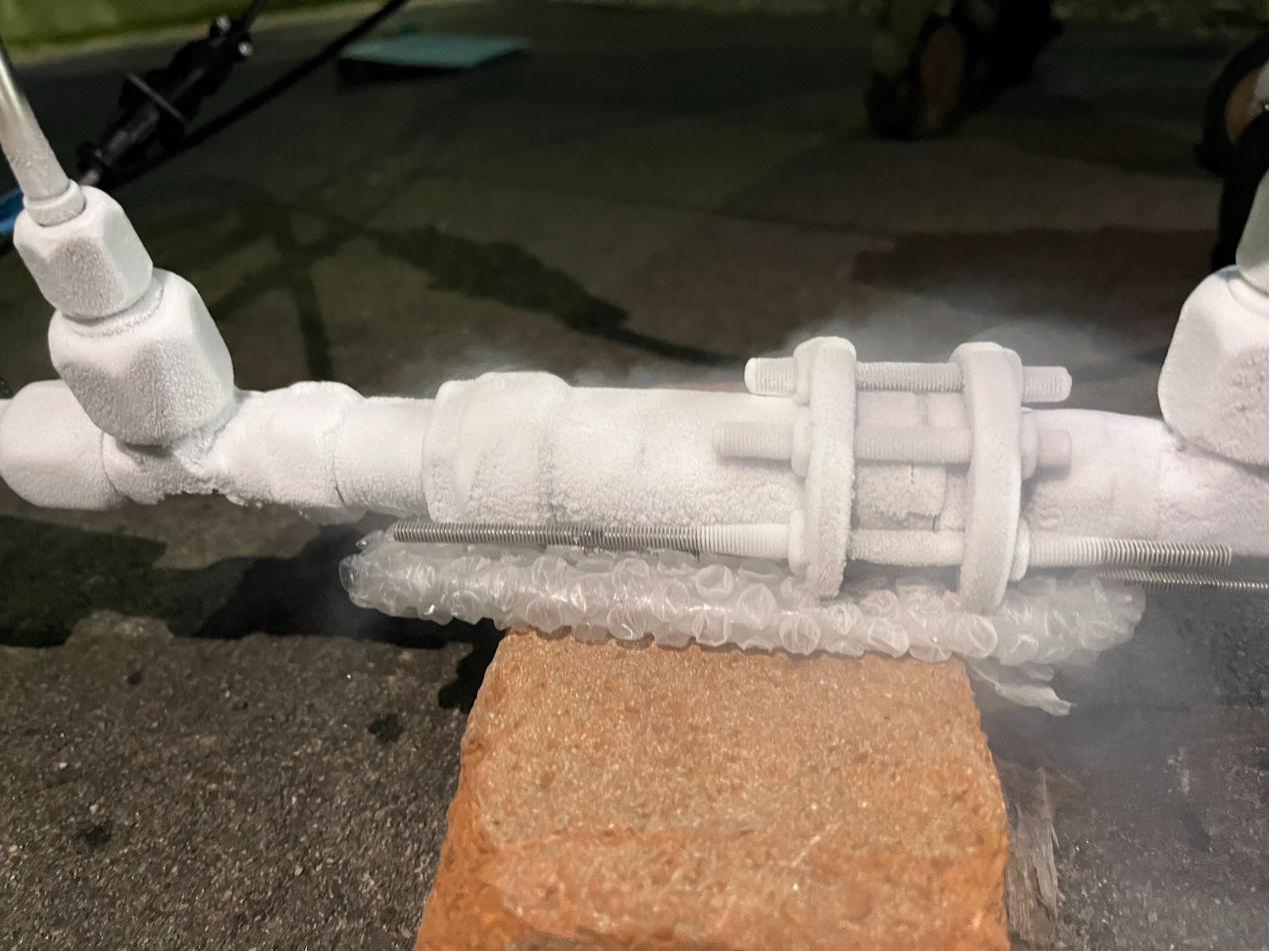
Limelight is MASA’s 24 ft liquid bipropellant rocket, targeting over 50,000 ft. Liquid oxygen is loaded on the pad through a fill valve, and the ground line has to separate from the vehicle cleanly at launch.
I led the design of that interface: a pneumatically actuated LOx fill valve and the quick disconnect plug that mates to it. It has to hold LOx at 850 psig MAWP, seal at cryogenic temperature, and then seal again immediately after the QD plug is pulled clear, under pressure, on a vehicle that is about to leave.
Sealing architecture
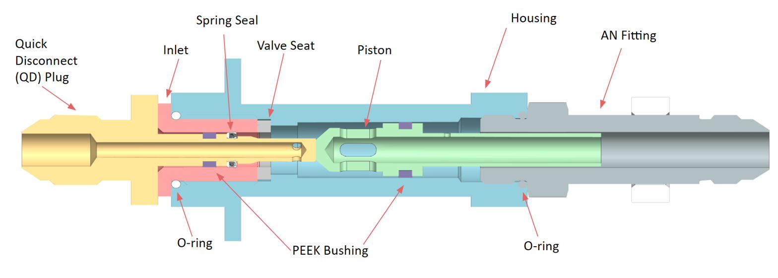
Two distinct sealing problems with different answers. Static sealing between housing components uses O-rings sized for squeeze at both ambient and cryogenic temperature.
The dynamic flight seal is the one that matters. When the QD plug withdraws, the pneumatic piston drives forward onto the valve seat, and that interface becomes the only thing between LOx and the outside world. A spring energized seal handles the plug interface, a PEEK bushing guides the piston so the closure stays concentric, and the PTFE seat takes the closing load.
Sizing the seat
The seat is the component the design hinges on, and it is not sized by pressure containment. It is sized by contact stress.
The geometry is a 45° conical stainless piston face closing onto the inner edge of
a PTFE seat: line contact around a 0.375 in bore, giving a contact length of
L = π·ID = 1.178 in. Closing force comes from the actuation spring
(k = 16.66 lb/in over 0.53 in of travel, 8.83 lbf) plus tank pressure acting on the
piston. The seat has to be stressed hard enough along that line to conform and
seal, without being driven so far that it stops sealing afterwards.
Choosing a contact model
Most of the work was deciding which contact model legitimately applied, and documenting why three candidates did not.
Roark, rigid knife edge on a plate. Assumes an infinite plate. The seat is 0.125 in thick with a real boundary, and the solution has a singularity at the contact point.
Roark, general case. Parameterised by the radii of curvature of two contacting bodies. This is line contact between a cone and an edge, not two curved surfaces.
Popov, elastic knife edge. The parameterisation the closed form needs cannot be extracted from this geometry in any meaningful way.
The model used was cylinder on a flat plate, the closest available form that does not violate its own assumptions here.
Result
Evaluated against the seat’s cryogenic yield target (0.8x compressive yield, 2,400 psi for PTFE), a PTFE seat carries 57.1 lbf normal before yielding. Resolved through the 45° face that is 80.8 lbf axial, of which 71.9 lbf can come from tank pressure, which works out to 271 psi of tank pressure against an 850 psig MAWP.
Running the same calculation across candidate seat materials:
| Material | Compressive E (psi) | Target Sy (psi) | Axial force at yield (lbf) | Equivalent tank pressure (psi) |
|---|---|---|---|---|
| PTFE | 69,050 | 2,400 | 80.8 | 271 |
| Vespel SP-1 | 350,000 | 5,920 | 103.4 | 356 |
| Vespel SP-21 | 420,000 | 5,280 | 68.7 | 226 |
| Vespel SP-22 | 475,000 | 4,800 | 50.3 | 156 |
| CR-D PEEK | 783,204 | 13,440 | 244.5 | 887 |
The trend is not monotonic in stiffness. The filled Vespel grades are stiffer than SP-1 but give up enough compressive yield strength to end up worse.
The valve was built with a PTFE seat, which is not a contradiction with the table. The seat is meant to yield: a polymer seat deforming into conformance against the piston face is what creates the seal, and a seat that stays fully elastic generally does not seal at all. The yield target is a bound on where conformance begins, not a limit the design has to stay under. The comparison shows how much load each candidate carries before it starts to conform, not which ones pass.
FEA
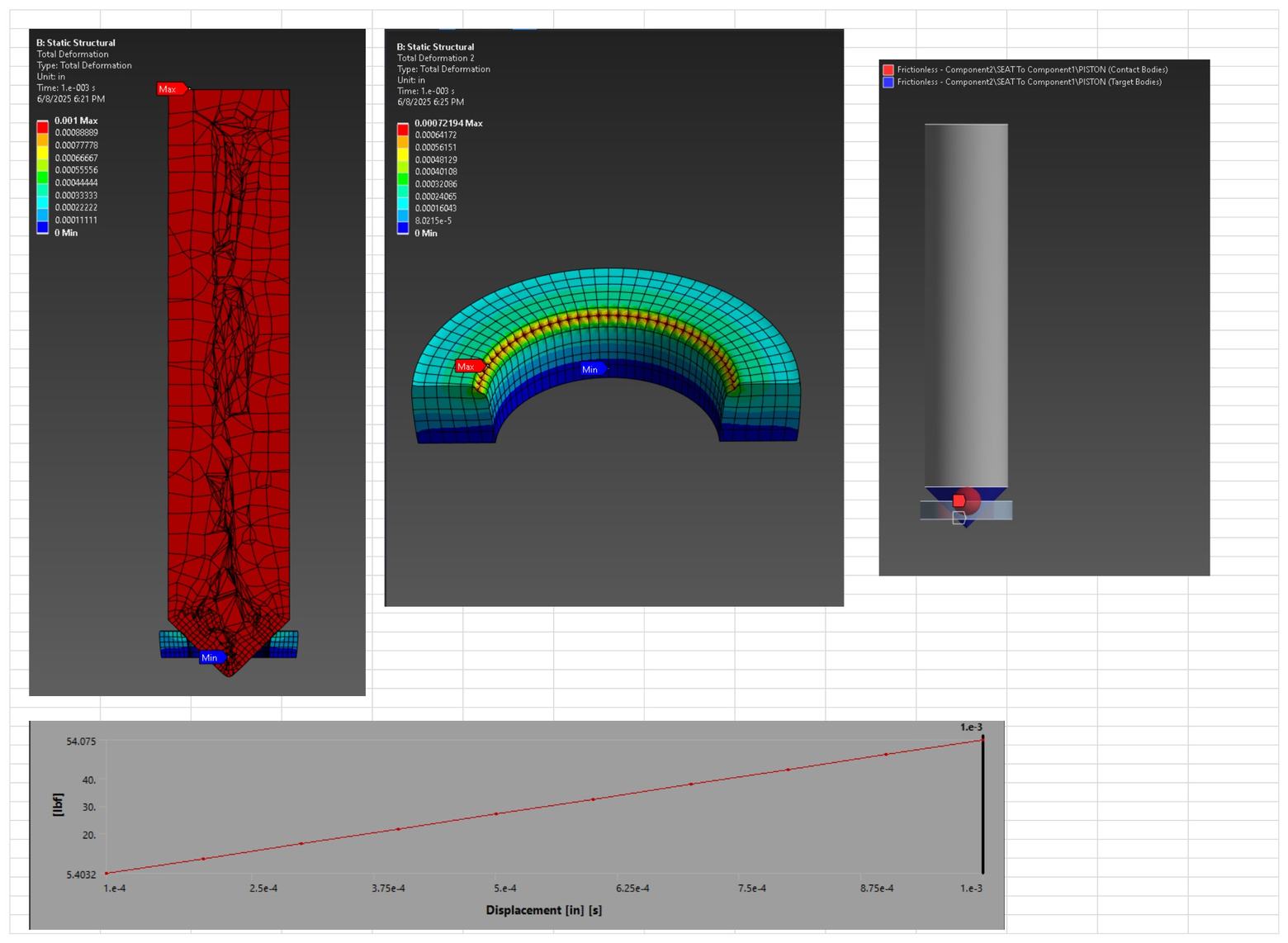
The hand calculation was checked against an ANSYS static structural model with a frictionless contact pair, sweeping closure displacement from 1x10⁻⁴ to 1x10⁻³ in and extracting reaction force. The model returns a linear 5.4 to 54.1 lbf across that range.
At the top of the swept range the model carries 54.1 lbf, against the 57.1 lbf the hand calculation gives as the load at which the PTFE seat begins to yield. The two agree to within about 5%, which is the useful result: the closed form model was not obviously wrong for this geometry despite none of the standard contact solutions fitting it cleanly. It also converts the answer into a more usable form. Yield is not reached at some abstract force, it is reached at roughly one thousandth of an inch of closure travel, which is a number the actuation design can be checked against directly.
Manufacturing
I produced the drawings for all eight custom components in Siemens NX and worked with the manufacturing team through the build. Parts were made in 304 stainless on a TL-1 CNC lathe, with manual mill and lathe operations for secondary features.
Every clearance was also evaluated as a tolerance stack at both room and cryogenic temperature, because the housing, piston, bushing and seals contract by different amounts. A fit that is correct on the bench can bind or leak at LOx temperature.
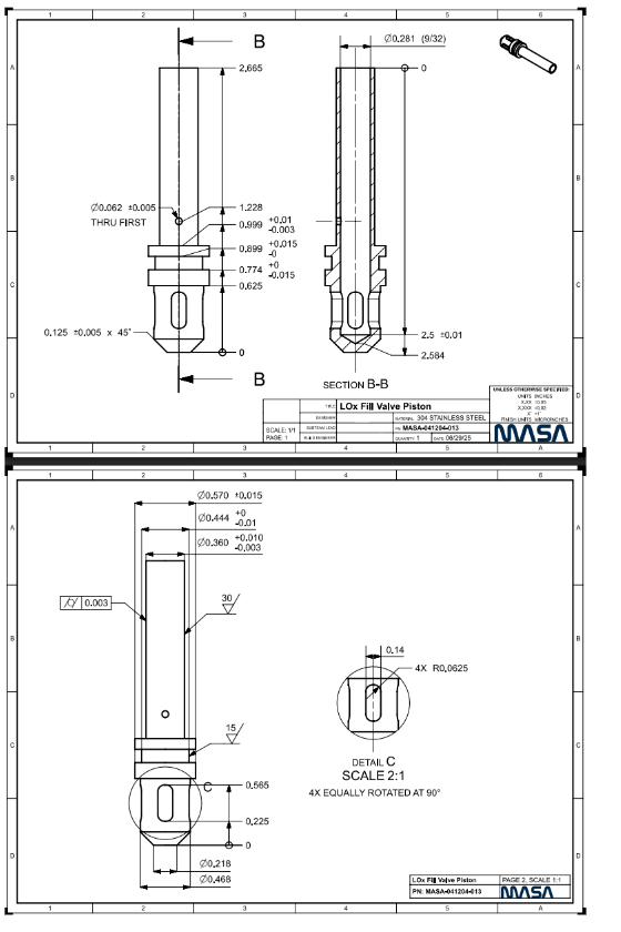
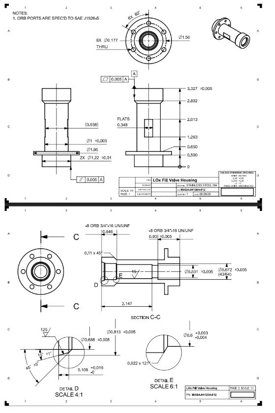
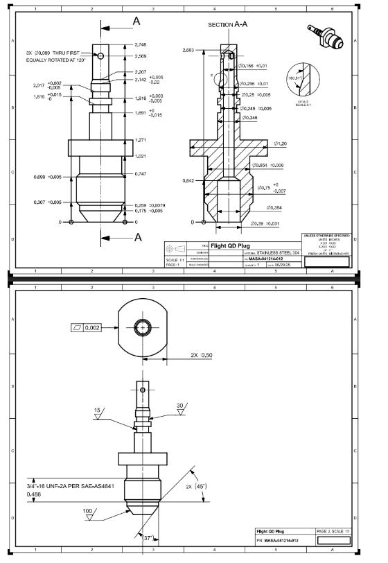
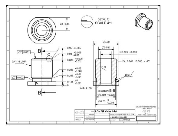

Drawing the parts is where most of the design actually got decided. The clearest example is the overall length. The valve was originally considerably longer, and drawing it up forced the question of how the bore would be produced: the drill bits available in house could not reach the depth the design called for. The valve was shortened to fit the tooling rather than the tooling being bought to fit the valve. The same pass settled surface finish callouts, which tolerances were realistically hittable on the available machines, and which surfaces could be CNC turned versus finished manually.
Proof testing
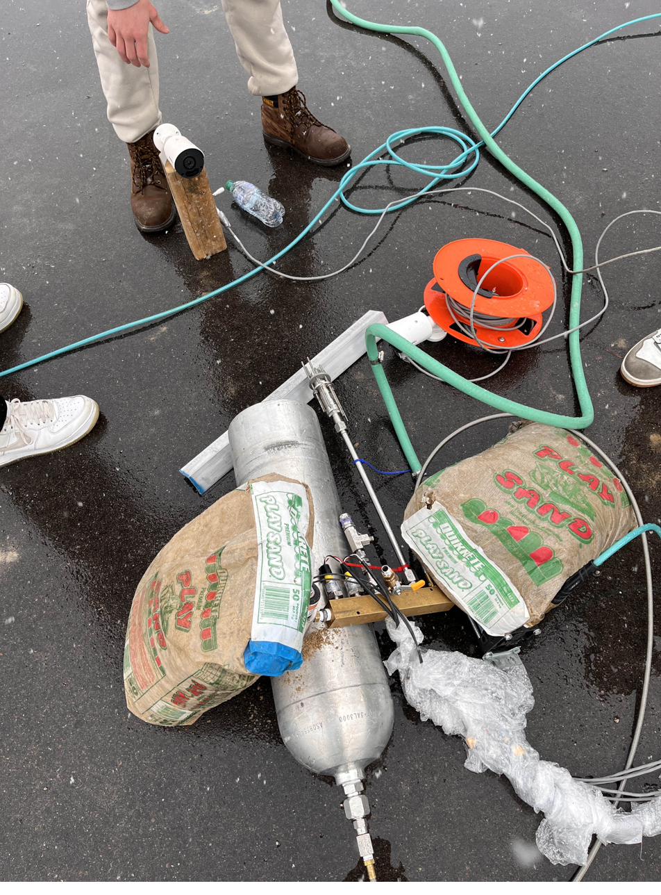
The valve and QD were hydrostatically proof tested to 1,275 psig, 1.5x the 850 psig MAWP. I led the test setup.
Separation test
The flight critical question is not whether the valve holds pressure. It is whether it reseals after the QD separates under pressure. That needs its own hardware and its own procedure.
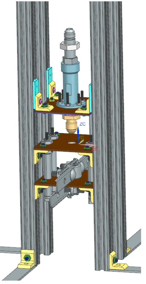
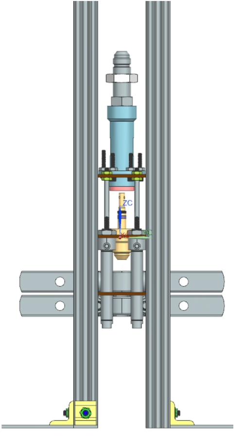
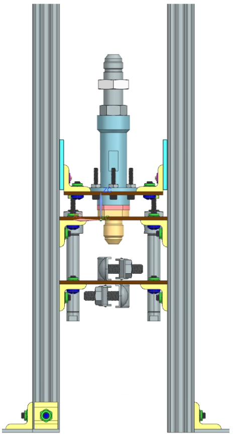
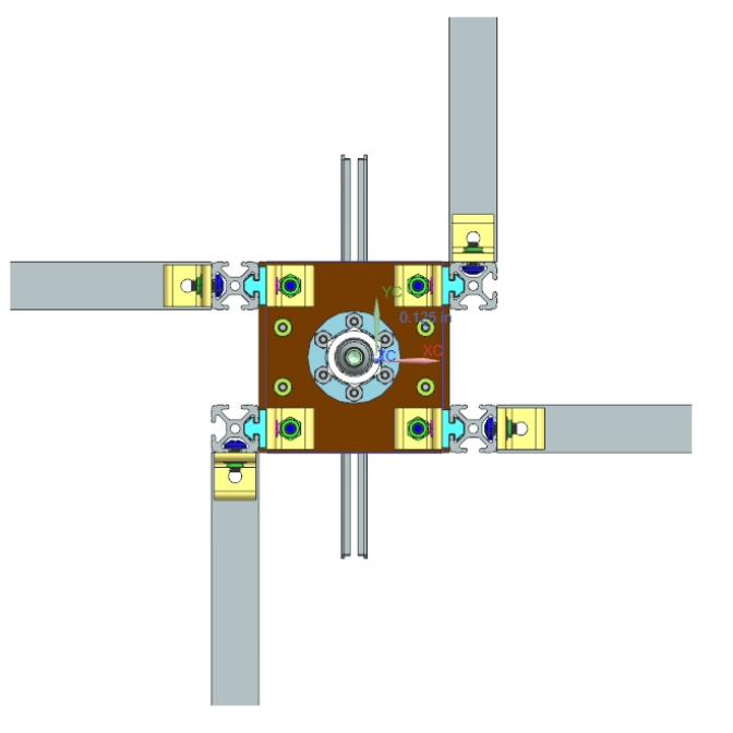
I designed the test apparatus: an extruded aluminium frame holding the valve vertically, with the QD plug on a sliding plate released under pressure so separation happens the way it will on the pad. I also authored the P&ID and the Standard Operating Procedure.
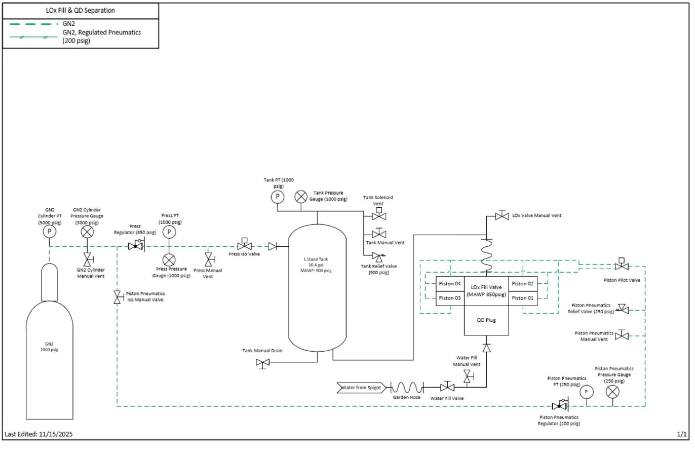
The SOP went through a dozen revisions across six weeks with review from the chief engineer, safety officer, ATLO lead and president. The changes were not cosmetic. One example: a manual vent was moved upstream of an isolation valve, because in its original position there was a configuration in which a trapped volume could not be vented. The document also carries the hazard analysis, a PPE matrix by role, the operations team roles, the notification and approval chain through EHS and the faculty advisor, and contingency procedures.
Cryogenic flow test
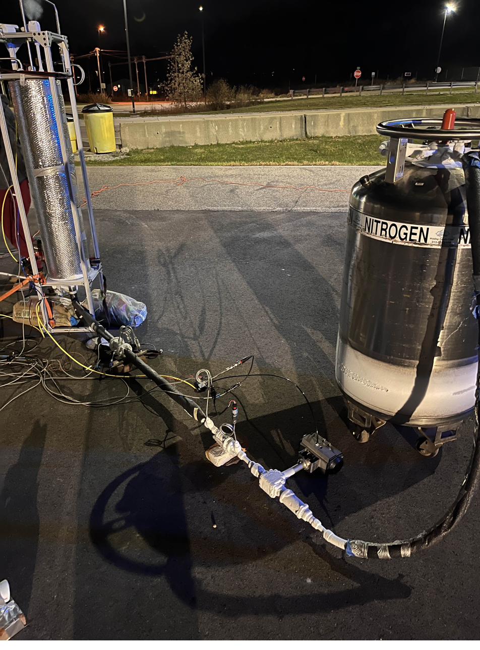
The cryogenic flow test asked the two questions that matter together: does the valve seal at LOx temperature, and does it flow cryogen when commanded open.
It failed, and it failed in more than one place at once. A leak path opened cold that was not present at ambient, and we never isolated which of three problems produced it.
Tolerancing. I had accounted for thermal contraction, but accounting for it is not the same as specifying tolerances tight enough for the application. The clearances called out were achievable by the shop and still too loose once everything was cold.
Axial alignment. The piston was initially guided by a single bearing, which did not hold alignment. A second bearing was added. It still did not hold.
Spring seal installation. Spring energized seals are fragile and installation sensitive in a way I had not designed around. Damage during installation is a credible leak path on its own.
Any of these could have caused it, and they may have compounded. The cause lived in the interactions between them, outside the analyses I had done correctly in isolation. We were working to a hard date for engine coldflow, and with several independent problems to chase there was not enough schedule left to diagnose and fix them all. The valve was replaced with a commercial off the shelf unit for the test.
What I took from it
Tolerancing a class of part is not the same as tolerancing a feature. For bearings, seals and similar bought in components, the manufacturer’s fit recommendations exist because the general purpose approach is not tight enough. I now go to the component specification before dimensioning the housing around it, rather than treating that as a check afterwards.
Installation is a design requirement. The spring seal has a narrow installation window, and a design that assumes it goes in cleanly is incomplete. Whether a part can be fitted correctly, by a real person, repeatably, belongs in the design alongside whether it seals.
Test procedures reviewed and approved through MASA’s chief engineer, safety officer and faculty advisor, and through University of Michigan EHS and the Wilson Student Team Project Center. Separation testing conducted at Mcity.