Regenerative Mooring Load Absorber
An inline inerter-spring-damper device that cuts snap loads on wave energy converter mooring lines and harvests energy instead of burning it as heat.
- Role
- Mechanical design, component selection, power electronics and control
- Context
- DOE SURE Program, Energy Harvesting and Mechatronics Research Lab, Prof. Lei Zuo, University of Michigan
- Dates
- May 2026 to August 2026
- closed-loop damping resistance tracked under live excitation
- 12 to 130 Ω
- flywheel synthesising ~140,800 kg of inertance
- 161 kg
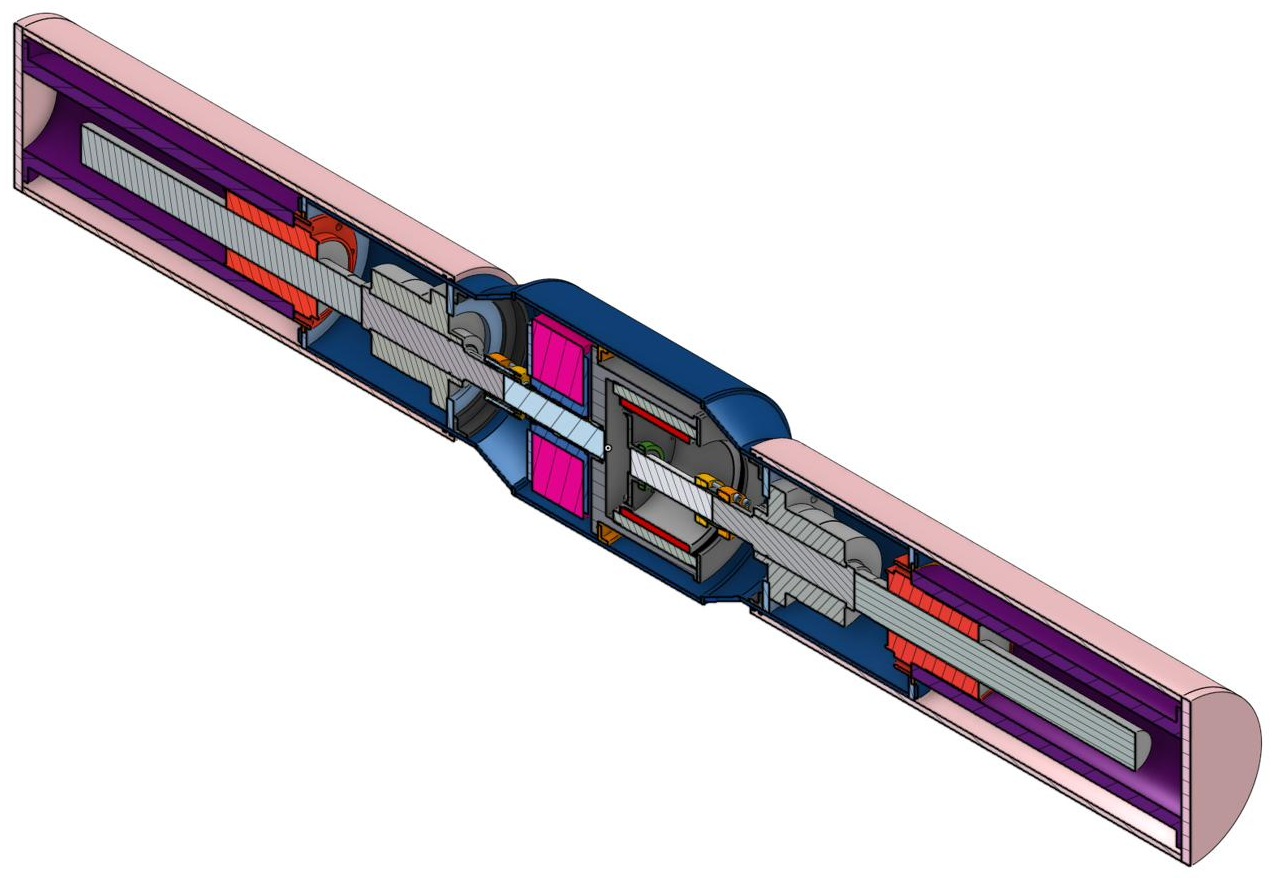
- sealed inline package replacing a section of mooring line
- ~2 m
The problem
Floating wave energy converters are deployed in the highest energy water we can find, because that is where the power is. They are held in place by mooring lines, and the lines are the part that fails.
When a line goes slack and then snaps taut, tension spikes. These snap loads reach the order of 1000 kN and drive both catastrophic failure and long term fatigue damage. Offshore mooring maintenance is expensive enough that line survivability is a real constraint on whether a WEC array is viable at all.
Existing mitigations mostly soften the axial stiffness of the line. That helps, but it uses only one of three available channels. A spring responds to displacement, and nothing in a conventional mooring responds to velocity or acceleration.
This project adds the other two. A damper resists velocity. An inerter resists relative acceleration, which is precisely the quantity that spikes during a slack to taut transition. The damper is electromechanical, so the energy it takes out of the line is regenerated rather than dissipated, which at full scale is enough to run condition monitoring sensors on a line that is otherwise unpowered.
Topology selection
Mechanical networks and electrical circuits are duals under the force-current mobility analogy, so the existing literature on circuit topology can be used directly to reason about how to arrange spring, damper and inerter. Spring maps to inductor, damper to resistor, inerter to capacitor.
Two things constrain the arrangement. A mooring line is in constant tension, so at rest the spring alone should carry the pretension and the damper and inerter should act only during wave excitation. And larger snap loads require larger inertance, so the topology has to stay well behaved as inertance grows.
Parallel stiffness with a series damper-inerter branch retains its performance as inertance increases. The fully parallel arrangement is mechanically simpler and has been studied for vehicle ISD suspensions, but degrades as inertance grows. The series configuration was selected as the target, and both were built so the difference could be observed in hardware.
Adapting to the sea, not to the design point
Sea states shift continuously in amplitude and frequency, so a device tuned to one condition is wrong most of the time.
Inertance is set by hardware, flywheel geometry and gear ratio, and is not practical to vary in real time on a sealed subsea device. Damping is. So the absorber adapts through real-time variable damping, and the damping is the part that carries the control problem.
Damping as a resistance, resistance as a control input
The damper is an electromechanical shunt damper. Linear motion drives a generator,
and the damping coefficient is set by the electrical resistance across the
generator terminals, c ≈ 1/R_shunt.
That turns a mechanical design variable into an electrical one, but only if the resistance can be varied without a bank of switched power resistors, and without throwing the harvested energy away as heat in them.
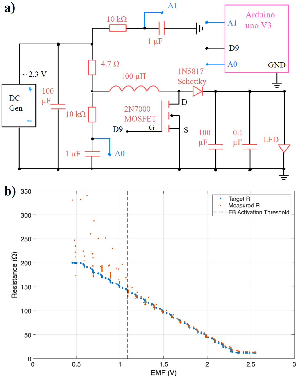
The solution was to emulate the resistance with a boost converter in discontinuous conduction mode, where the input resistance seen by the generator is a function of duty cycle:
R_in = (2·L·f / D²) · (1 − V_in/V_out)
Because the converter is a boost stage rather than a dissipative load, the energy extracted from the line is routed to the converter output and stored, not burned. Damping control and energy regeneration are the same mechanism.
Control is closed loop: a feedforward term from the relationship above, with a proportional correction driven by real-time current sensing. A supply voltage sweep confirmed accurate tracking of a commanded resistance from 12 Ω to 130 Ω.
Prototypes
Two bench scale prototypes, one per topology, mapping each circuit element to hardware: flywheel to inerter, spring to stiffness, generator to damper.
| Series inerter-damper | Parallel inerter-damper | |
|---|---|---|
| Gearing | Planetary stage, clutch dependent | Fixed, N = 1 |
| Flywheel inertia | 1.76 x 10⁻⁵ kg·m² | 1.26 x 10⁻⁵ kg·m² |
| Flywheel mass | 65.8 g | 67.4 g |
| Spring | k = 4 N/m over a 33.5 cm stroke | same |
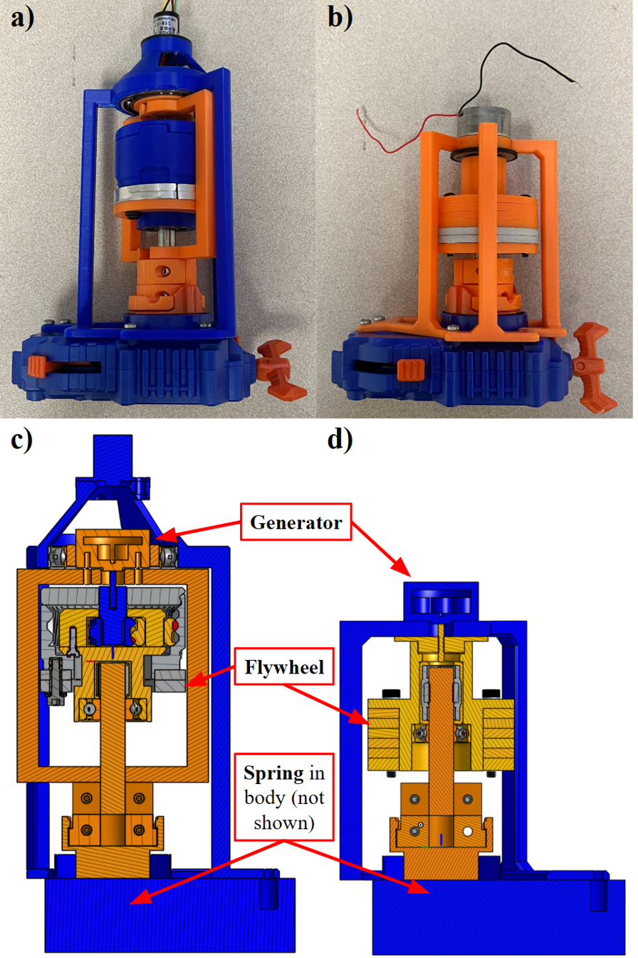
Both were fabricated in house: PLA printed on a Bambu H2D, with bearings, shafting, springs and fasteners from McMaster-Carr. The input stroke comes from a Beyblade QuadDrive launcher, an off the shelf toy that delivers a repeatable ripcord driven pull, suggested in the lab as a cheap way to realize the concept and kept because it worked.
The units shown are the last of several iterations, and the iterations went in two directions. Modularity, so flywheel inertia could be varied rather than fixed at build time, which is what lets one rig test a range of inertance. And friction reduction, since parasitic friction is the thing that swamps the measurement at this scale: additional bearings to hold axial alignment, and a slip ring to take the electrical path off the rotating structure.
The series configuration uses a one-way clutch, so the flywheel freewheels rather than holding a fixed speed relationship to the input. The effective gear ratio therefore changes with clutch engagement, and inertance in that configuration is not reducible to a single constant. That only became obvious in hardware.
Testing
Excitation came from repeated drop tests at three masses (647 g, 1100 g, 1403 g) on both prototypes, with the controller commanding a damping law as a function of measured generator EMF.
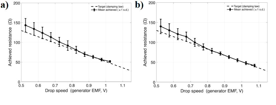
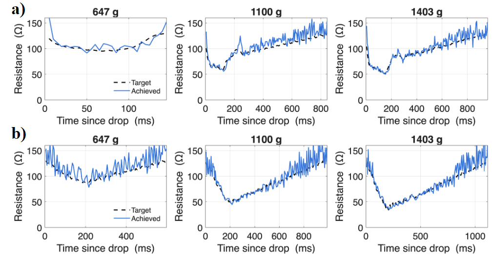
Achieved resistance tracked the commanded damping law across all three masses and both topologies. Tracking degraded at low drop speeds and high commanded resistance, for a reason worth stating explicitly.
What did not work, and why
The two topologies cannot be fairly compared at bench scale. Parasitic mechanical friction in the printed prototypes is the same order of magnitude as the EMSD damping being commanded, so any difference between series and parallel is buried in it. This is why no load reduction figure is claimed here. The concept was realized and the damping control was validated, but the mechanical signal to noise at this scale does not support a quantitative reduction result.
Stroke length limits resolvability. 33.5 cm is not enough travel to resolve the damping and velocity reduction the device is meant to produce.
Low input speed starves the current sense. At low drop speeds the generator current is too small to measure reliably, which saturates the feedback loop at high commanded resistances. The obvious fix, lowering excitation force to sit in a better part of the range, makes the current problem worse, so it is not available.
Each of these is a scale artifact rather than a failure of the concept, which is what makes a Froude-scaled prototype the correct next step rather than a redesign.
Full-scale design
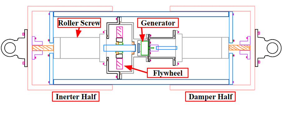

The full-scale device packages the same topology into a sealed unit roughly 2 m long that replaces a section of mooring line. It has not been built. What follows is the design state as handed off.
Motion conversion. A Rollvis HRV 100 roller screw with a 35 mm lead converts line extension into rotation, configured screw-rotates and nut-translates, on a Rollvis BU8 support bearing.
A roller screw rather than a ball screw, because the governing load case is a snap event. A ball screw carries load at a small number of point contacts, and shock loading at a point contact is what brinells a raceway. A roller screw distributes the same load along line contacts across many threaded rollers, raising both the static rating and the fatigue life substantially. For a device whose purpose is absorbing sudden tension spikes, unattended, for years, that is the difference between a component sized for the duty and the first thing to fail.
Inerter branch. A solid 4340 steel flywheel, ⌀440 mm outer, ⌀140 mm bore,
150 mm thick, roughly 161 kg, driven through a GMN FE 8072 Z 25 sprag clutch so it
freewheels rather than being rigidly tied to the input. With b = J·(2π/L)² at a
35 mm lead, that is an equivalent inertance of about 140,800 kg from a 161 kg part,
which is the whole reason the topology is worth its mechanical complexity.
Damper branch. A Kollmorgen KBM-118 frameless direct drive motor, coupled 1:1 to the screw. At the representative RMS axial velocity of about 1.4 m/s the rotor turns at roughly 2,400 rpm, with peak excursions near 6,070 rpm, at a continuous electrical target in the 7 to 10 kW range and about 1,560 N·m of torque.
Frameless because of integration and sealing. The device already provides a rotating shaft, bearings and a sealed housing, so a frameless rotor and stator drop straight into structure that exists anyway. A housed servo motor would bring its own bearings, housing and shaft coupling, duplicating all of it, and its seals and grease packed bearings would not survive an oil filled chamber at depth. Direct drive also removes a gearbox, which over a five to ten year unattended deployment is the component most likely to end the device’s life.
Being precise about status: the frameless architecture is settled, the speed range
follows from kinematics, and the power class follows from c·v². The specific
frame is a power and envelope match from the Kollmorgen catalogue rather than the
output of a vendor down-select, and the winding is open pending the bus voltage
decision, which sets it. Several comparable frameless torque motors would likely
serve.
Shell. A split weldment. Two ⌀350 mm sealing tubes are welded to conical transitions at 30° from the axis in 10 mm wall, then bolted through flanges with static O-ring face seals onto a central ⌀520 mm bulge tube housing the flywheel and motor. Machining a single bulged shell is not practical at this diameter, and the split approach keeps tight tolerance where it is actually needed, on the sealing tubes, rather than across the whole envelope.
Dynamic sealing. Parker FlexiSeal NLI as the primary seal with an SLI wiper, cross-section 05, on the ⌀350 mm rod, with a Co-Cr-Ni spring energizer and F3 guide tapes. This replaced a polyurethane BT/BR stack disqualified on surface speed: the rod velocities here exceed what the material tolerates.
Two fluids, for two reasons. The flywheel chamber is gas filled, because a flywheel spinning in oil loses a large amount of power to windage and the inerter branch cannot afford it. The motor and damper side is oil filled and pressure compensated, which is what lets a thin walled housing survive at depth without being built to take full external pressure. A mechanical face seal on the rotating screw shaft separates the two volumes.
Anti-rotation. Guide rods inside the sealed volume react roughly 10 kN of tangential load, keeping the nut from spinning with the screw.
Restoring force. A full scale helical spring is not an option. Providing the required stiffness at this load would need about 49 m of free length, longer than the device by more than an order of magnitude. The restoring force comes instead from a DublinOffshore buoyancy tank, moving the spring element out of the inline package entirely.
Next steps
- Quantify the energy actually harvested by the EMSD. Regeneration is achieved but not yet measured.
- Build a 1:2 Froude-scaled prototype where parasitic friction no longer dominates
- Develop a current-sensing driven control law targeting load mitigation directly, rather than resistance tracking as a proxy
Presented at the SURE Program Symposium, August 2026. Funded by the U.S. Department of Energy. Conducted in Prof. Lei Zuo’s Energy Harvesting and Mechatronics Research Lab, under Wei-Ying Wong and Prof. Zuo. I authored the poster; both appear as co-authors.