Badminton Shuttlecock Launcher
A self-directed machine design project: a court-portable feeder that serves a repeatable shot, built around a single-motor iris feed mechanism.
- Role
- Everything. Requirements, concept generation, downselect, CAD, prototyping.
- Context
- Personal project
- Dates
- June 2025 to present, intermittent
- concept families generated before downselect
- 7
- motors, after the drive was reworked
- 2 to 1
- target feed rate into a 6 in zone
- 12/min
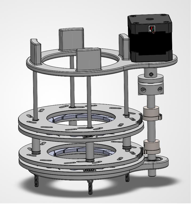
Status, September 2026. This is not finished and this page does not pretend otherwise. The feed mechanism is designed and has been through several printed iterations. The launcher head and the platform are in CAD. Nothing is assembled. What follows is the design process to date.
Why this exists
I play badminton on Michigan’s collegiate team. Practising a specific shot alone is close to impossible, because somebody has to feed you the shuttle, and a human feeder gets tired and inconsistent long before you do. Commercial feeders exist and are expensive.
I also wanted a project that would let me run a full machine design cycle end to end, on my own, with nobody assigning the requirements.
Requirements
I started by writing down what the machine has to do, then turning each objective into something measurable, because “feeds shuttles well” is not a specification.
| Objective | Functional requirement |
|---|---|
| Feeds a shot consistently without player input | At least 12 shuttles per minute, landing within a 6 in diameter target zone |
| Introduces controllable variance to challenge the player | Programmable random targeting within the 6 in zone, and placement anywhere in a 20 in diameter zone |
| Can be taken to a court by one person | Under 10 kg, fits in 19.75 x 46.5 x 30 in, a car trunk, and is hand carryable |
Concept generation
I sketched seven concept families rather than converging early, splitting the problem into launch, feed and base.
Working through the alternatives is where most of the reasoning happened. The four bar guiding rail has a lower actuation range and more parts than a rack and pinion, but demands far less precise interfacing between components. The spring stoppers on the catapult bridge protect the motor and the stoppers themselves, but need a steeper front stopper angle to launch effectively. The cart base allows a lower centre of mass than the tripod, but the tripod stores and adjusts better.
Full design document, including all seven concepts and the reasoning behind each.
Downselect
I scored the concepts against the functional requirements in a weighted matrix, weighting FR1 highest as the core function, FR2 and FR3 lower as flexibility and convenience, and adding manufacturability and creativity as design criteria. Manufacturability was weighted heavily, because I intend to actually build this.
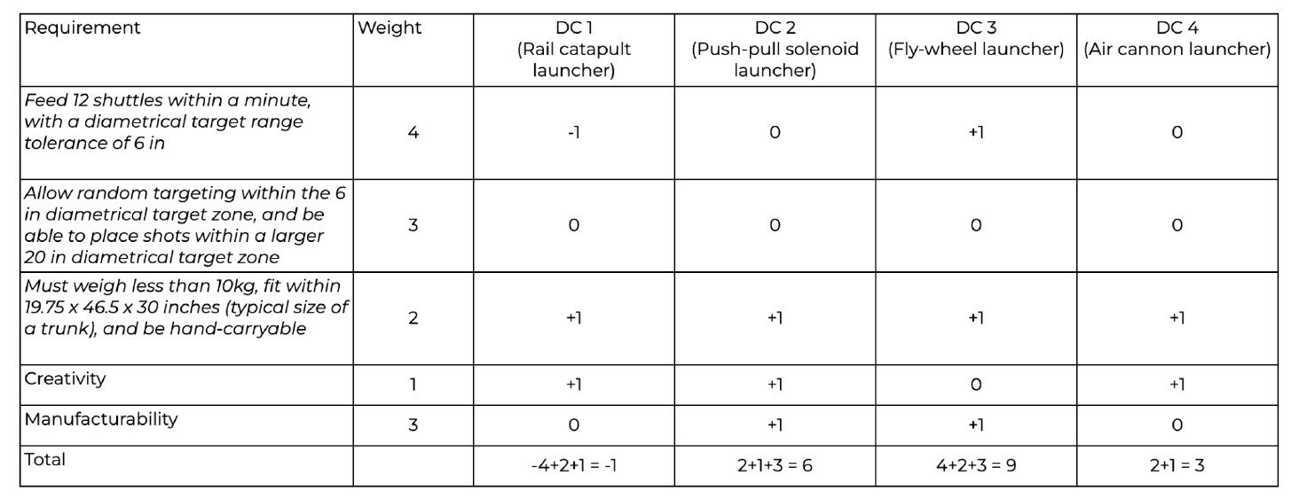
The matrix surfaced a problem with the requirements, not just the concepts. Every concept scored zero on part of FR2, because every launcher I had drawn targets along a line, and none of them can place a shot anywhere in a circle. The fix was architectural rather than a matter of picking a better concept: add a motor giving the whole launch platform planar rotation, turning a target line into a target zone.
The flywheel launcher won. It gives a variable launch angle at the head, which lets the supporting frame sit lower than the solenoid concept needs, which makes the whole machine more stable.
The feed mechanism
Feeding turned out to be harder than launching.
A shuttlecock is an awkward object to handle: light, asymmetric, easily damaged, and the feathers vary between shuttles and degrade with use. The mechanism has to grip one shuttle, hold the rest back, release exactly one, and do it repeatably on shuttles that are not identical to each other.
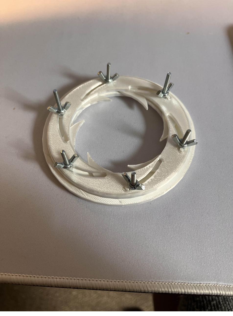
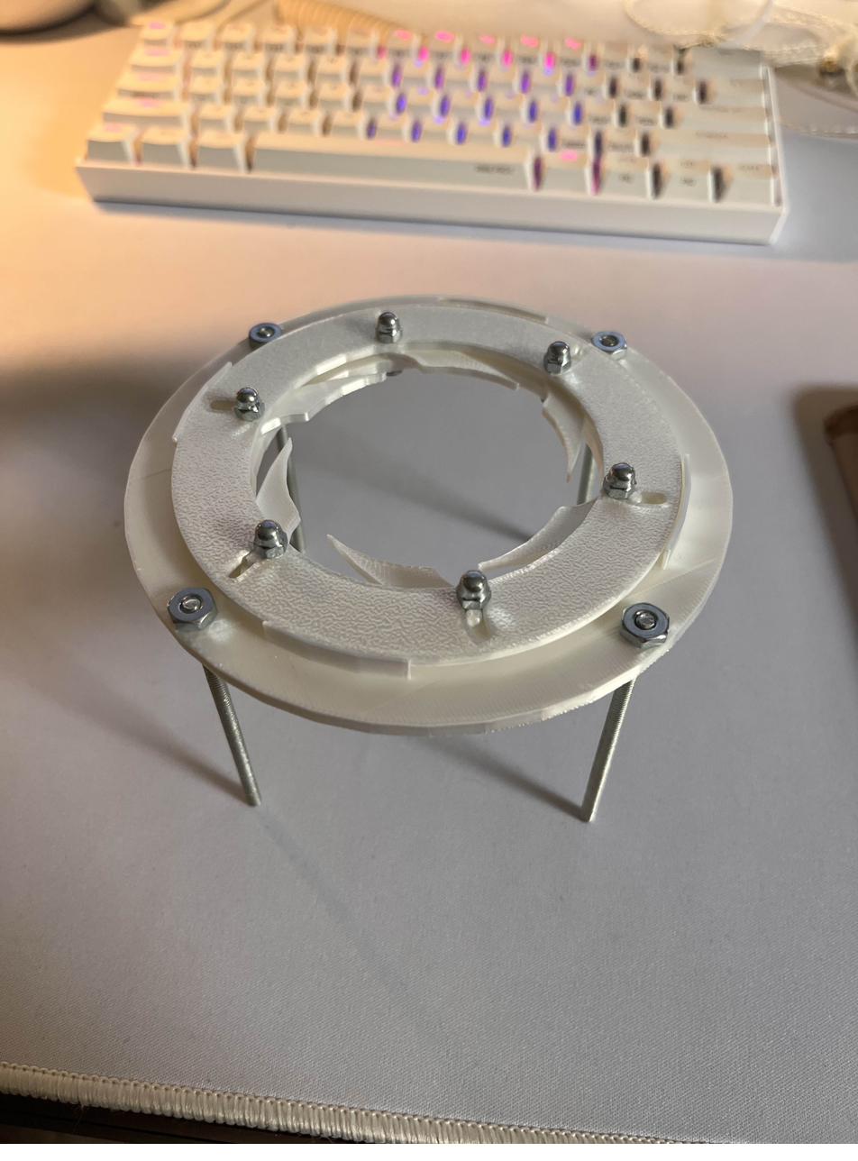
The approach I settled on is a double iris: two stacked shutter stages, the upper holding the column of shuttles back while the lower releases one, then handing off.
Six curved blades, not four. Because feather condition varies between shuttles, fewer blades grip less consistently. Six blades also let the mechanism grip further up the feather cone without the shuttle losing balance, which a four blade arrangement cannot do.
Simplifying the drive
The original concept used two motors, one actuating each iris stage, sequenced against each other in software.
The current design uses one. A single timing shaft carries two sector gears phased 180° apart, each meshing with the ring gear of one iris stage. As the shaft turns through 90°, the sectors engage in turn, so the four step feed sequence, hold, release, catch, reset, falls out of the geometry rather than out of coordinated motor commands. This removes a motor, removes the synchronisation problem entirely, and makes the sequence impossible to get out of phase.
The mesh did not work on the first attempt. The centre distance had to be opened past the theoretical 71.5 mm to clear an interference between the sector and ring gear teeth.
CAD, and changing my mind about it
I started this in CATIA V5, deliberately, because I had not used it and it is widely used in industry. I moved to SolidWorks partway through.
The reason is not that CATIA was bad. It is that I was spending project time learning an interface instead of designing a mechanism, and the mechanism is the point. Learning a new tool is a fine goal. It is a bad goal to attach to a project that is already the harder of the two things you are trying to do.
Credit
The two-level shutter feed concept is heavily inspired by RiedeProjects’ video Badminton Shuttle Feeder Part 2: dispensing mechanism (diaphragm). I found it while researching how to practically achieve the motion I had sketched, and built from there. The six blade geometry, the single motor timing drive and the mechanical detailing are mine.
Build sequence
- Build the flywheel launcher head
- Assemble the two DOF rotational platform and mount the head to it
- Integrate the feed mechanism with the launcher
- Add the shuttle storage device
- Full build
- Control code